Feature #610
closed
Implement lightsw IoT device
100%
Description
This is code for the ESP8266 to act as a lightsw. It is an extension of the generic ESP8266 code I'd worked on previously, but redesigned to adhere to the defined protocols for Ironman.
Files
Related issues
 Updated by Hammel almost 8 years ago
First pass is pushed. It compiles but isn't tested. And there are no stubs yet for actually controlling the light switch. This is just a communications implementation.
Updated by Hammel almost 8 years ago
- Project changed from Iron Man to Sensors
- Category deleted (
Device Node)
Updated by Hammel almost 8 years ago
- Severity changed from 01 - Critical to 04 - Low
Updated by Hammel over 7 years ago
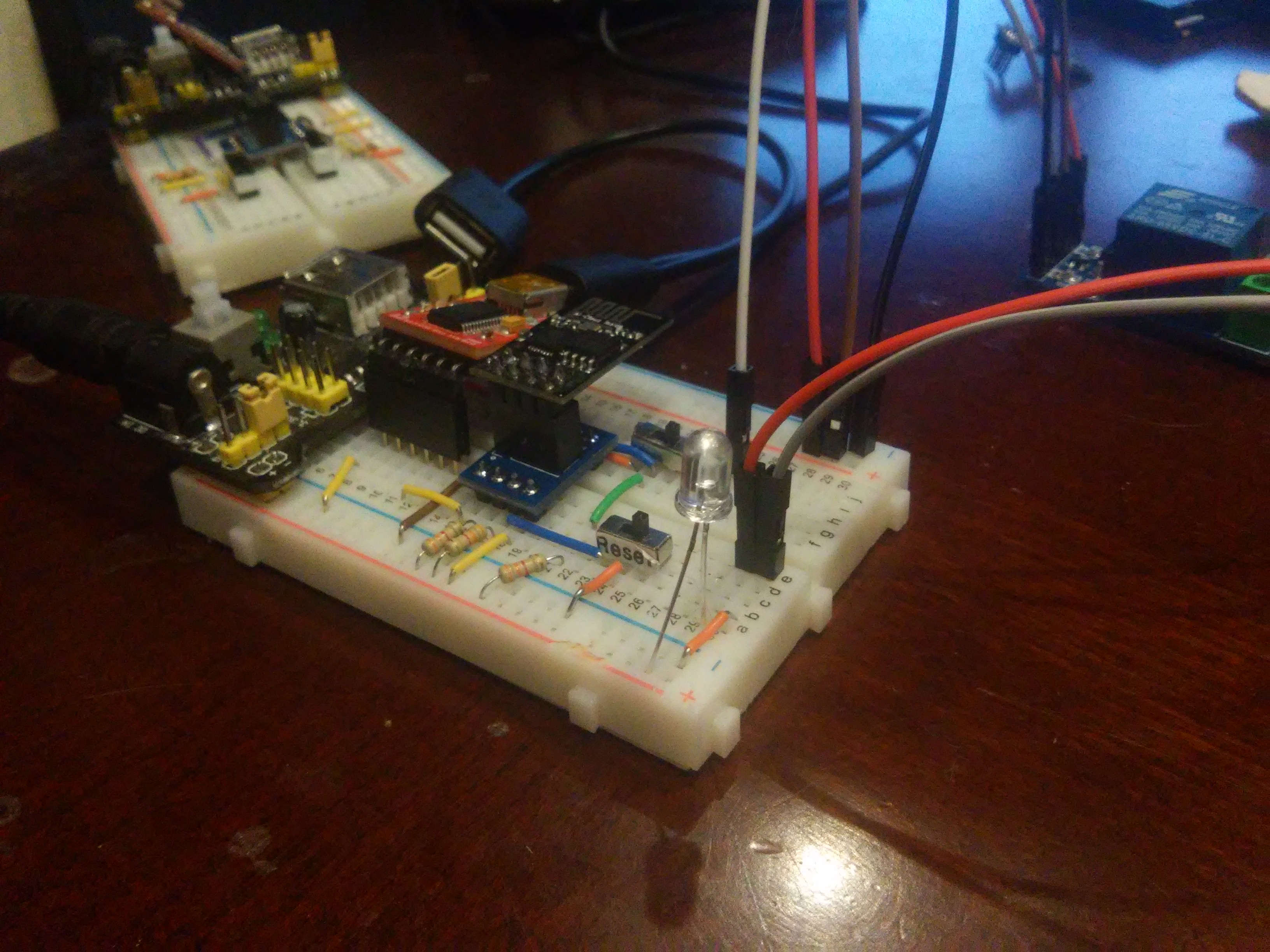
First, getting back to working with the ESP-01 took a while. My layout on the breadboard was klunky so I reworked it and things stopped working. It took quite a bit of time before I found the problem.
If you power the ESP-01 from it's own 3.3v source, then the FTDI board used to program it must have the same ground. If not then any attempt to program gets stuck while the PC tries to connect to the ESP-01 bootloader. I'll post some pics for this setup later.
After fixing that I can upload and run the old esp8266 sample code I had. It will boot into the WifiManager hot spot for configuring the board using 192.168.4.1 and the AP "imiot". However, the lightsw code, which was based on that, doesn't work.
Now I need to run meld to compare the two modules and see why the new code isn't booting into the wifi manager.
Also: If I use the Arduino IDE, I have it pointing at 1.6.7. I should update this to the 1.8.4 version, using "latest" as a symlink and pointing ~/bin/arduino to that. See also: https://github.com/esp8266/Arduino.
Updated by Hammel over 7 years ago
There is a prime example, nearly identical to what I'm trying to do, on this website:
https://www.forward.com.au/pfod/ESP8266/GPIOpins/ESP8266_01_pin_magic.html
The section on Driving a Relay and Reading a Push Button using GPIO0 / GPIO2 is what I need to implement.
FYI: my current code for imlightsw wasn't working because of my incorrect use of GPIOs. The example code above should fix this (along with some hardware mods to the breadboard).
There's also this article, which is probably a little closer: http://acoptex.com/project/304/basics-project-021e-esp8266-esp-01-wi-fi-module-5v-relay-modules-webserver-at-acoptexcom/
Updated by Hammel over 7 years ago
- % Done changed from 30 to 40
Whoopeeeeee!! The first working version of imlightsw is now committed and pushed. The working version has a Config Mode switch that allows me to place the ESP-01 in Wifi AP Configuration mode at power up. If the switch is disabled then we enter Operational Mode. In Operational Mode the Relay switch is toggled on and off every three seconds.
I'll post a pic of this later just to show the Relay LED on.
Now it's on to cleaning up the code so inbound messages can control the state of the relay.
Updated by Hammel over 7 years ago
Added support for building with either serial console or blue LED using SERIAL environment variable.
Added support for switching to Pair Mode after power on using same button as Config Mode.
- First I need to verify the web server is setup properly and I can reach it.
- Then I need to implement/verify the REST API for the device.
- Then I need to integrate AES encryption for decoding commands and encoding responses.
The first two shouldn't take long, though implementing a command to enable/disable the device has to be tested from the monitor.
The last one may need some fiddling to get right. Hopefully the Arduino AES library support 128 bit encryption which is what the monitor is using.
Updated by Hammel over 7 years ago
- % Done changed from 40 to 50
The web server in imlightsw is working now. The IoT sends a multicast message that the monitor responds to by going to the IoT web server, passing a UUID. The IoT device then contacts imrest to register with that UUID.
At that point the test stops because it was run on my desktop and there is no imgpio available. I can fake this if needed to complete registration testing.
Next up is AES message passing.
Updated by Hammel over 7 years ago
- Connect a light to the relay.
- Connect power to the relay.
- Test that a request to toggle/set the state changes power to the light.
- Make sure current state is stored so the state can be reapplied on the next power up. Either that or reset to off on power up.
Most of this is physical stuff. I just need a small battery and LED for the demo or maybe get clever with something a bit brighter.
The code changes are small because I mostly have code for toggling the relay though they are untested. Storing/reloading the state is not handled yet, though that's pretty simple too. I do need to return new state data to the monitor so it can save it. I also need to test the device get function that returns current state data.
Updated by Hammel over 7 years ago
- % Done changed from 70 to 90
First, hardware: The relay can take 2.8V or higher as input so doesn't really need 5V power, but I kept it that way. But I removed the line level converter because that wasn't needed after all. Next, I tied an LED to the 3.3V line and the output from the relay to that LED and the associated ground. I no longer tie GPIO0/GPIO2 to control the relay, however. That didn't work and probably wouldn't have worked because I was using the config switch differently than the reference schematic.
So I switched to using the Rx pin as a digital output. I pull it low to enable the relay and high to disable it. Works like a champ.
I updated the imlightsw code to demo the relay going on and off at 1s intervals. This code is pushed, but I need to clean it up so that- Use of the Rx line is no longer a compile time option - it's the default (doesn't affect serial output so I can still see debug message in minicom).
- The demo relay blink should be a compile time option to verify that the circuit is still working.
- All the old code using GPIO0/GPIO2 for the relay should be removed, if any is still left in there.
Once that is cleaned up I can close this issue since I have another issue (RM #669) to complete testing of the get_state API and another (RM #604) for setting light switch state.
Updated by Hammel over 7 years ago
- Severity changed from 04 - Low to 01 - Critical
Updated by Hammel over 7 years ago
- Status changed from In Progress to Closed
- % Done changed from 90 to 100
All code cleaned up. It's production ready except for the previously noted new features.
Code pushed. Closing issue.